
As mentioned in my previous post, there are several improvements that need to be adressed for the prototype. Robin and I decided to focus on the sturdiness of the prototype. This post will describe how we set out to make it more compact.
We decided that the board that we used to plug in together the different components was not solid enough and therefore we wanted to replace it with something more sturdy. We set out to make a printed circuit board (PCB) of our circuit. We used the semi-freeware EAGLE (free for our simple use) to make the design of the circuit.
Here is a picture of the electrical circuit.

The associated printable circuit. Please note that PCB’s can be printed in several layers (up to 6), for simplicity reasons we only printed a mono-layer. The red lanes represent wires that we use on the other side of the board to connect the two points together.
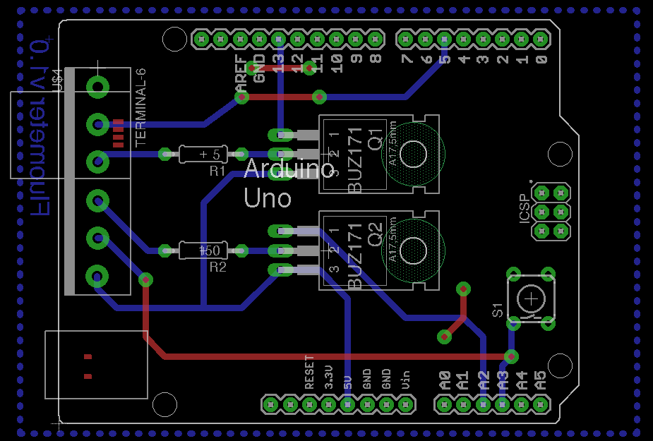
The design was then printed on a transparent sheet. The sheet was then used in the PCB lab at EPFL. WIth the use of photoresist, an oven to heat it up, an UV lamp to cure the exposed photoresist and acid to remove the cured copper we ended up with a PCB representingour circuit.. Please find here a tutorial summarizing different parts of making DIY printed circuit board without having to have so much horrible chemicals.

The board being printed, we could then proceed to the mounting of our circuit and different components. I got to do some soldering, which Robin taught me how to do, which was very cool. Here is the finished board.
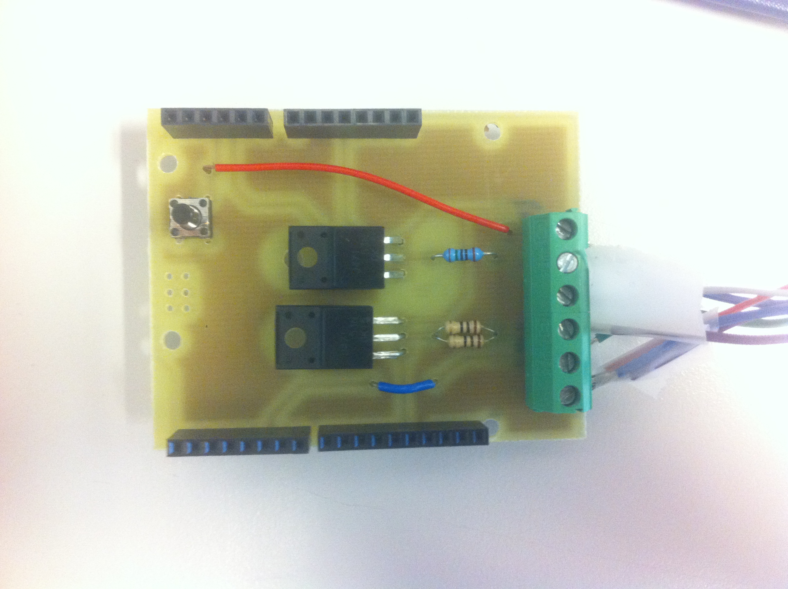
We then associated the board with the Arduino and the LCD shield
 .
.
We also added solidified the prototype by gluing everything together and drilling a hole in the box so that we can control the measurements from the outside without rogue light rays penetrating the box.
Github repository with all the necessary files : The eagle file (.brd) is in the FluoShield folder

Pingback: First Prototype tested with Arsenic | biodesign for the real world